








Last time around, we revisited (or maybe visited for the first time for some of the readers) a set of concepts regarding a proper database structure. Let’s finish that review with tables and their relationships.
Written by Rafael Victoria-Pereira
Yes, theory is boring, but very necessary for what’s ahead. It’ll help you ease into the more complex constructs that await you later in this sub-series. Having said that, let’s get back to it!
Table Relationship Types
If you didn’t know already, you’ve realized by now that the whole primary-foreign key thing links two tables together. However, by itself, this is not enough to define the relationship. It’s also important to know the type of relationship. Relationships between tables can be zero, one, or many. Zero means that the record does not have to exist in the target table; one with zero implies that it can exist; one without zero implies that it must exist; and many simply implies many. Looking at our database, you’ll find that all the current relationships are one-to-many: each child table can have one or more records with foreign keys (in most cases, a name column) linking back to a single record of the parent table. You must be able to define these relationships in a sentence. For instance, each record on the Students table can have one or more records on the Classes table. I’ll be using this type of reasoning to review existing relationships (and create new ones) between the tables in our database.
Understanding Identifying and Non-Identifying Relationships
There’s another perspective on the inter-table relationships. If the parent table's primary key is included in the child table's primary key, then their relationship is an Identifying relationship, and the child table is said to be dependent on the parent table. An example of this would be an intermediate table, typically used to implement a many-to-many relationship at the database level. This table would sit between the two other tables (the ones that actually have the many-to-many relationship) and have one-to-many relationships with both. To maintain the link between the two original tables, the intermediate table needs to include both tables’ primary keys in its own primary key. Intermediate tables are also known as association tables.
As you might have gathered, a non-Identifying relationship is the exact opposite of what I just described: a relationship in which the child table holds the primary key of the parent table as a foreign key, and that key is not part of the child table’s primary key.
Referential Integrity
Referential integrity works as its name suggests: it ensures the integrity of referential relationships between tables defined by primary and foreign keys. In a relation between two tables, one table has a primary key and the other a foreign key. The primary key uniquely identifies each record in the first table. In other words, there can be only one record in the first table with the same primary key value. The foreign key is placed in the second table in the relationship and contains a copy of the primary key value from the related table.
This concept is not new. You have probably been enforcing it in your programs for years. However, it’s also possible to enforce it directly in the database, ensuring it behaves consistently regardless of the program (RPG or not) that manipulates the data. As we evolve toward a new paradigm in which the IBM i is more integrated with an organization's IT landscape, ensuring this consistency – or referential integrity – is of paramount importance. Using primary and foreign keys on every table will ensure consistency regardless of where and how your data is being used.
Entity Relationship Diagram Notation
Using sentences is a good way to evaluate one relationship, but we’ll need to describe all the relationships between tables in our database. Using text to do that will get really confusing, really fast, especially if your IBM i database is a fundamental piece of your IT infrastructure, with all the weight that carries: big, complex, and interconnected with other applications built on other platforms. So we’ll use a picture instead – humans can handle visual information much faster and more efficiently than textual information – we’ll use an entity relationship diagram (ERD). An ERD describes the tables and their relations in a visual and very informative way, once you get used to its notation. I’ve already hinted at one of the two most used notations: using zero, one, and many (or N, as it’s more commonly known) to describe a relationship is part of Chen’s notation, and it’s very common to find it in ERDs. The other one is Crow’s Foot notation. It’s based on the same idea but uses symbols instead of numbers to depict the relationship’s modality and cardinality, which are the indicators of the business rules around a relationship. Cardinality refers to the maximum number of times an instance in one entity can be associated with instances in the related entity. Modality refers to the minimum number of times an instance in one entity can be associated with an instance in the related entity.
Cardinality can be 1 or many, and the symbol is placed on the outside ends of the relationship line, closest to the entity. Modality can be 1 or 0, and the symbol is placed on the inside, next to the cardinality symbol. For a cardinality of 1, a straight line is drawn. For a cardinality of many, a foot with three toes is drawn. For a modality of 1, a straight line is drawn. For a modality of 0, a circle is drawn. Figure 1 shows the possible combinations of modality and cardinality.
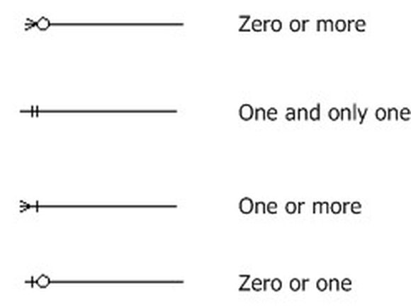
Figure 1: Crow’s foot basic notation
Identifying and non-identifying relationships are also part of this notation: a dashed line indicates a non-identifying relationship, and a continuous line, as shown in Figure 1, indicates an identifying relationship. Naturally, this shows only one side of the relationship.
Let’s look at some examples of actual relationships defined using this notation. Figure 2 depicts a couple of relationships between tables. First, you’ll see the relationship between Student and Seat. In this relationship, one and only one student fills one and only one seat: it’s a one-to-one relationship. In the second example, you’ll find the most common type of relationship: one Teacher teaches one or more Classes: it’s a one-to-many relationship. Even though you can, theoretically, define many-to-many relationships, these are not easy to manage efficiently in actual databases. It’s always best to use an intermediate table and have two one-to-many relationships between the three tables (the original two plus the intermediate table).
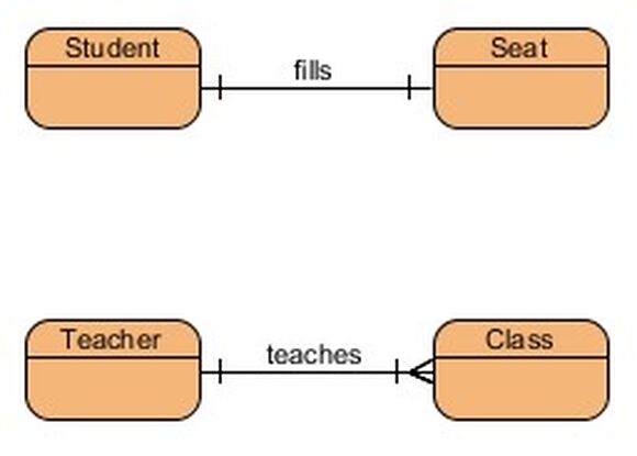
Figure 2: Crow’s foot relationship examples
Even though we have discussed theory, it’s directly applicable to DB2 for i databases. We will come back to these diagrams later, and you’ll see how they relate to the database design in a one-to-one relationship (pun intended).
That’s it! Didn’t hurt, did it? In the next article, we are going to start making some changes to the database structure – time for some hands-on work, putting all this theory to good use!

Rafael Victória-Pereira has more than 20 years of IBM i experience as a programmer, analyst, and manager. Over that period, he has been an active voice in the IBM i community, encouraging and helping programmers transition to ILE and free-format RPG. Rafael has written more than 100 technical articles about topics ranging from interfaces (the topic for his first book, Flexible Input, Dazzling Output with IBM i) to modern RPG and SQL in his popular RPG Academy and SQL 101 series on mcpressonline.com and in his books Evolve Your RPG Coding and SQL for IBM i: A Database Modernization Guide. Rafael writes in an easy-to-read, practical style that is highly popular with his audience of IBM technology professionals.
Rafael is the Deputy IT Director - Infrastructures and Services at the Luis Simões Group in Portugal. His areas of expertise include programming in the IBM i native languages (RPG, CL, and DB2 SQL) and in "modern" programming languages, such as Java, C#, and Python, as well as project management and consultancy.
MC Press books written by Rafael Victória-Pereira available now on the MC Press Bookstore.
 |
||
 |
|
Evolve Your RPG Coding: Move from OPM to ILE...and Beyond Transition to modern RPG programming with this step-by-step guide through ILE and free-format RPG, SQL, and modernization techniques. List Price $79.95 Now On Sale
|
|
||
 |
|
Flexible Input, Dazzling Output with IBM i Uncover easier, more flexible ways to get data into your system, plus some methods for exporting and presenting the vital business data it contains. List Price $79.95
Now On Sale
|
|
||
 |
|
SQL for IBM i: A Database Modernization Guide Learn how to use SQL’s capabilities to modernize and enhance your IBM i database. List Price $79.95
Now On Sale
|

 Business users want new applications now. Market and regulatory pressures require faster application updates and delivery into production. Your IBM i developers may be approaching retirement, and you see no sure way to fill their positions with experienced developers. In addition, you may be caught between maintaining your existing applications and the uncertainty of moving to something new.
 IT managers hoping to find new IBM i talent are discovering that the pool of experienced RPG programmers and operators or administrators with intimate knowledge of the operating system and the applications that run on it is small. This begs the question: How will you manage the platform that supports such a big part of your business? This guide offers strategies and software suggestions to help you plan IT staffing and resources and smooth the transition after your AS/400 talent retires. Read on to learn:
LATEST COMMENTS
MC Press Online