Increase your database understanding with this free IBM tool.
Your physical database implementation plays a key role in the performance and extensibility of your application. Because the AS/400's integrated relational database was so easy to use, many programmers created physical files and logical files without giving much thought to the database model. This approach has resulted in many unwieldy physical databases that are hard to understand.
Data modeling tools help teams build efficient new databases as well as maintain existing database implementations. IBM Data Studio is a relatively new, no-charge tool from IBM that includes support for physical data modeling. This physical data model supports DB2 for i databases. This functionality even includes some support for DB2 for i objects created with DDS.
IBM Data Studio doesn't provide support for logical data modeling, but the physical data model support can improve your database understanding and maintenance. If your team is looking for an IBM tool that supports both logical and physical data modeling, you could download a trial evaluation copy of the IBM InfoSphere Data Architect product.
IBM Data Studio manages all of the tasks through the use of projects. To launch Data Studio and create a new project, perform the following steps:
- From the Windows Start menu, click All Programs > Data Studio > Data Studio Client.
- From the File menu, select the New task and create a Data Design project. In this example, the project name is Project2. Click Finish to finalize the project creation process.
To start the process of generating a graphical representation of the IBM i physical database model, right-click on the newly created Data Design project and select the New > Physical Data Model task as shown in Figure 1.
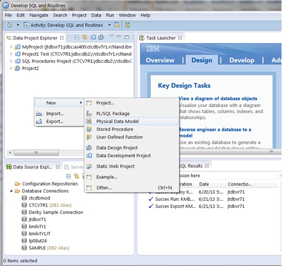
Figure 1: Create a new physical data model.
The next step is identifying the target database to model, as shown in Figure 2. The first input field will contain the name of the newly created Data Design project. The next input field allows you to name the data model. In this example, the name is My Database Model. Obviously, the database value will be DB2 for i, and then you need to select the operating system version that is installed on your target IBM i system. In this case, an existing database is being modeled, so select the "Create from reverse engineering" check box. After selecting this option, click Next to continue.
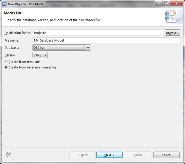
Figure 2: In the New Physical Data Model window, identify the target database to model.
Selecting the connection for the DB2 for i server that houses the database you want to analyze is the next step. Figure 3 contains the Select Connection page. Create a connection for your DB2 for i server by clicking on New.
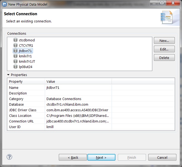
Figure 3: Specify the connection for the DB2 for i server.
The New Connection window in Figure 4 presents the input fields for defining a new database connection. The default naming convention results in the generation of a connection name based on the database or host name for your IBM i server. From the JDBC driver drop-down list, you will find several driver options. The majority of IBM i programmers select AS/400 Toolbox for Java because this JDBC driver is available at no charge. The IBM Toolbox for Java is automatically included with the IBM i operating system software. You can also download this JDBC driver from the JTOpen website. JTOpen is the open-source version of the IBM Toolbox for Java.
The Host name is the TCP/IP host name of your IBM i server. This interface also allows you to override the default schema value (the authorization ID) that is used while running the SQL routine for any SQL statements that contain unqualified table or view references. If a value is not specified, the default value is Authorization ID. The IBM i equivalent of an authorization ID is a user profile.
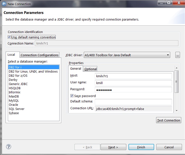
Figure 4: The New Connection properties page looks like this.
You can either verify that you have set up the connection correctly by clicking Test Connection or move the process along by selecting Next. The next window provides you with an optional Data Privacy Modeling step that allows you to associate the new connection with a physical data model. This is an optional step. Click Next to continue.
You are then presented with the Filter window shown in Figure 5. This is an optional step that allows you to specify particular schemas that are available or not available to a database connection. It's often a good idea to exclude some of the IBM-provided schemas that start with letter Q.
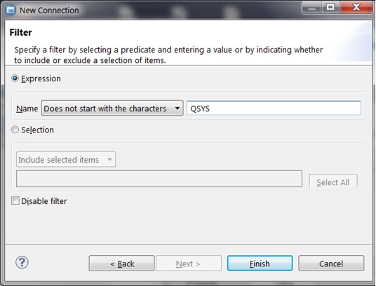
Figure 5: The Filter page allows you to specify a schema.
Click Finish to complete the creation of the connection. With the database connection created, left-click to choose that connection on the Select Connection window (Figure 3). Click Next to move on to the next step in the modeling process.
Figure 6 displays the Select Objects page where you can specify the schema (or library) that contains the DB2 objects that you want to reverse engineer. You can select a single schema or multiple schemas. You can select the schema from the list of schemas associated with the schema or type in a filter string to narrow the list to your target schema. After selecting the schema, click Next to advance to the final step in the process.
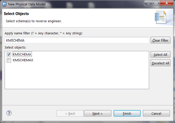
Figure 6: Select the schema.
The Database Elements page (shown in Figure 7) allows you to select the type of database objects that can appear in your physical data model. In this example, tables are the only object type that will be included in the diagram. After selecting the required database element types, click Finish to build the physical data model.
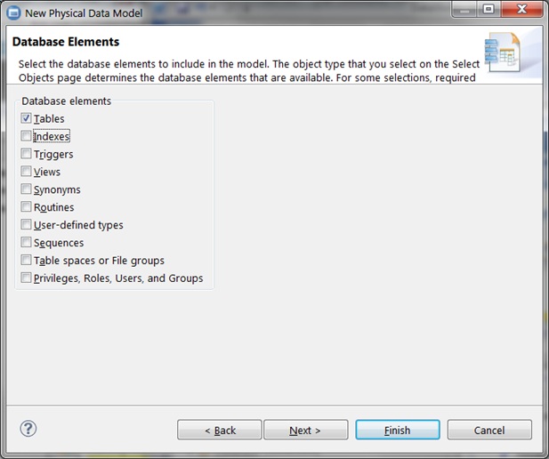
Figure 7: Select database element types.
After the physical data model is built, you will be taken to the Physical Data Model Editor view (refer to Figure 8). To generate the visualization diagram, your first step is to expand the data object (ctcdbv7r1.rchland.ibm.com) associated with the physical data model object (My Database Model.dbm). After the data object has been expanded, you need to right-click the Diagrams folder and click New Overview Diagram.
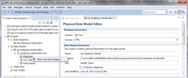
Figure 8: This is the Physical Data Model Editor view.
The first input field in the Overview Diagram Selection dialog box (shown in Figure 9) allows you to supply a name for the diagram. The Implicit relationships option enables Data Studio to find relationships between DB2 objects by looking for common column names. Data Studio uses foreign key constraint definitions to find explicit relationships between tables. The "Include selected elements" section enables you to include a subset of the objects from the data model in the diagram. If a selected DB2 object references an unselected DB2 object, the "Automatically select referenced elements" checkbox controls whether or not that object is included in the diagram.
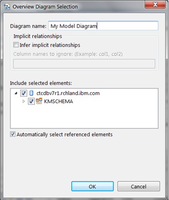
Figure 9: Here's the Overview Diagram Selection dialog box.
Figure 10 contains the data diagram generated by Data Studio for the selected database objects. The boxes in the diagram (for example, Project) are the tables in the data model's schema. The identifiers associated with the connecting lines between tables are the constraint names. Data Studio enables you to rearrange objects in the diagram, change text formatting, and add notes to the diagram to make the diagram easier to read. You can also add database objects that were not selected earlier in the process.
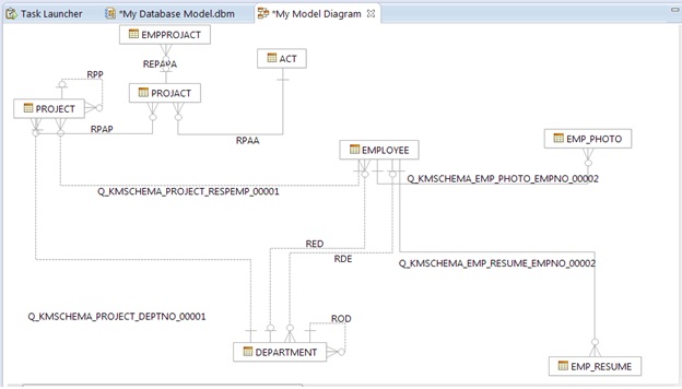
Figure 10: The data diagram output looks like this.
The column definitions for a table or physical file can be accessed from the model diagram by first clicking the table object in the diagram. After the table is selected, right-click and click Show Properties View as shown in Figure 11. After that task has been selected, the lower-right pane of the window displays a table properties view. Clicking on the Columns tab provides a list of the columns in the table and the attributes for each column.
Data Studio also allows you to print the diagram or save the diagram into an image file so that the diagram can be easily shared with other team members.
The Data Studio physical data model and data diagram tooling does support DB2 for i objects created with data description specifications (DDS). Data Studio categorizes logical file objects as views, so keep that in mind when selecting database object types to include in your physical data model.
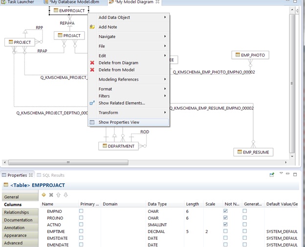
Figure 11: The Show Properties view allows you to see table properties.
Hopefully, you can now appreciate how much easier it is to understand your database design with the physical data modeling capabilties that the Data Studio tooling offers. Data Studio provides more than physical modeling capabilities; a complete listing of the features that are supported with DB2 for i databases can be found here.


 IT managers hoping to find new IBM i talent are discovering that the pool of experienced RPG programmers and operators or administrators with intimate knowledge of the operating system and the applications that run on it is small. This begs the question: How will you manage the platform that supports such a big part of your business? This guide offers strategies and software suggestions to help you plan IT staffing and resources and smooth the transition after your AS/400 talent retires. Read on to learn:
 Business users want new applications now. Market and regulatory pressures require faster application updates and delivery into production. Your IBM i developers may be approaching retirement, and you see no sure way to fill their positions with experienced developers. In addition, you may be caught between maintaining your existing applications and the uncertainty of moving to something new.
LATEST COMMENTS
MC Press Online